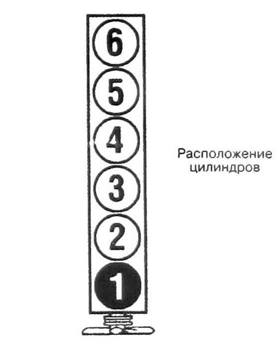
Inline 6-cylinder engine Fire order 1-5-3-6-2-4
Total information
Working volume - 4.2 l
Bore and stroke - 92.964 x 102.108 mm
Compression ratio - 10:1
Cylinder numbers - 1-2-3-4-5-6
The operating order of the cylinders is 1-5-3-6-2-4
Camshaft
Neck diameter
- Exhaust camshaft, neck No. 1 - 29.957 - 25.982 mm
- Exhaust camshaft journals 2-7, as well as all intake camshaft journals - 26.954 - 26.980 mm
Axial play
- Intake camshaft - 0.0508 - 0.2007 mm
- Exhaust camshaft - 0.0432 - 0.2134 mm
Cam lift
- Intake camshaft - 6.960 - 7.061 mm
- Exhaust camshaft - 7.188 - 7.290 mm
Cylinder head
Deviation limit from plane - deviation 0.05 mm for every 100 mm of surface
An exhaust manifold
The limit of warping of the mating surface is 0.076 mm
Tightening torques of threaded connections - Nm
Camshaft cover bolts - 12
Camshaft sprocket bolt
Intake valves
- Stage 1 - 20
- Stage 2 - Turn 100°
Exhaust valves (drive device)
- Stage 1 - 24
- Stage 2 - Turn 135°
Cylinder head bolts (The tightening sequence is shown in illustration 9.13)
- Stage 1 Tightening the long head bolts (1 - 14) in the given sequence until the moment - 30
- Stage 2 - Tighten the same bolts in the same sequence to 155°
- Stage 3 Tighten bolt No. 15 with a torque of 7 Nm and tighten to an angle of 120°
- Stage 4 Tighten bolt No. 16 and 17 with a torque of 7 Nm and tighten to an angle of 60°
Plugs for service holes in the cylinder head - 5
Crankshaft pulley bolt
- Stage 1 - 149
- Stage 2 - Rotate 180° (half a turn)
Drive chain
- Tensioner shoe bolt - 26
- Tensioner guide bolt - 10
- Tensioner bolts - 24
- Upper chain guide bolts - 10
- Intake manifold bolts - 10
- Exhaust manifold bolts - 24
Bolts securing the drive disc to the crankshaft
- Stage 1 - 24
- Stage 2 - Turn 50°
Front engine casing bolts - 10
Crankshaft rear oil seal housing bolts - 10
Pan mounting bolts
- Side – 24
- End - 10
Pan cover bolts - 10
Oil pump bypass valve plug - 14
Engine mount nuts (top and bottom) — 71
Bolts securing the engine mount brackets to the frame - 10
Valve cover bolts - 10
