Note. On engines of 3.8 liters of release 1990-1992. the EGR system was not installed.
Engines with a displacement of 3.1 liters (EGR vacuum valve)
General description
1. Exhaust gas recirculation system (EGR) used to reduce the content of NOx compounds formed due to high temperatures during the combustion of fuel (nitrogen oxides) in exhaust gases. This is achieved by lowering the combustion temperature. To reduce the temperature, the exhaust gases during the operation of the engine in economy mode are returned from the exhaust system to the intake manifold. The presence of these gases leads to a decrease in the combustion temperature and, in turn, to a decrease in the content of NOx compounds formed during fuel combustion.
2. Installed on engines 3.1 l exhaust gas recirculation system (EGR) consists of a negative or positive backpressure EGR valve, a manifold vacuum source tube and an electronically controlled vacuum valve solenoid (EVRV), The control that manages this source.
Examination
3. If the EGR flow is too high, the combustion of the fuel is weakened, causing the engine to run unevenly or even stall. Excessive EGR causes the engine to stall after a cold start or idle when decelerating, and the vehicle jerks at economy speeds or idles rough. With the EGR valve constantly open, the idle mode may not work at all.
4. With too little or no EGR flow, the combustion temperature of the fuel rises excessively with increasing engine speed or when the engine is under load. As a result, detonation, engine overheating, and failure of the exhaust gas composition and quantity test may begin.
5. The following checks will help you identify problems that affect the operation of the exhaust gas recirculation system. When the job description recommends lifting the recirculation valve diaphragm, wear heat-protective gloves to avoid burns.
Exhaust gas Recirculation valve
6. The valve of the recirculation system is controlled by a normally open solenoid, which, when voltage is applied to it, actuates the valve that supplies vacuum to the system. The solenoid, powered by the ECM, activates the EGR system and continuously monitors flow through the EGR thermostat. The ECM controls the EGR system when three conditions are present: coolant temperature must be above 45°C, throttle position sensor (TPS) indicates that it is partially open, and the MAP sensor is in the middle of the operating range. If a malfunction is detected in the vacuum solenoid, thermal switch or vacuum source, the system issues code 32.
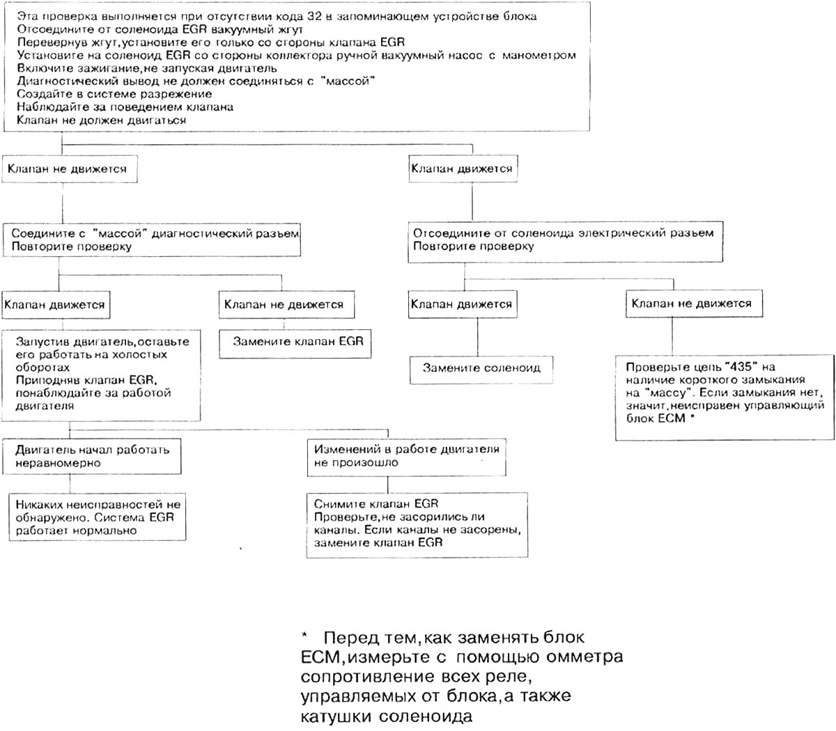
7. The attached diagram shows the sequence of checking the EGR valve, illustrated by photographs.

{{Открыть большую картинку в новом окне}} »
7.7a. ECM Controlled Exhaust Gas Recirculation Valve Test Sequence Diagram (only for 3.1L engines)

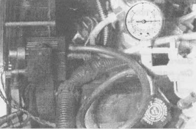
7.7b. Create a vacuum in the EVRV valve on the EGR system side and, without shorting to "mass" diagnostic output of the ALDL unit, observe any movement of the EVRV valve... | 
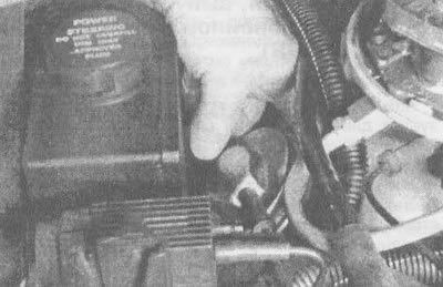
7.7c....by placing your finger directly on the diaphragm inside the EGR valve body (there should be no valve movement) |
Exhaust gas recirculation control system
8. When code 32 is displayed, the lamp glows "SERVICE ENGINE SOON" or "CHECK ENGINE" ("Check engine") you can immediately indicate the most likely sources of malfunction of the recirculation system. The EGR system takes into account factors such as the engine coolant temperature sensor, TPS sensor, MAP sensor, BARO sensor, torque converter clutch position, and engine speed when selecting the optimal recirculation timing.
9. Vacuum valve control solenoid (EVRV) exhaust gas recirculation systems (EGR) when the solenoid is turned on from the EGR, it is guided by the pulse width, the value of which is set by the ECM. Under normal conditions, the valve is open and the vacuum source is the transmitted signal. The ECM is responsible for turning the EGR system on and off ("duty cycle") by closing the circuit "435" (gray wire) on "mass". Duty cycle is zero percent (exhaust gases are not recycled), when the shift lever is in the neutral or park position, when the TPS input signal is below the set value, and also when the signal is "WOT" ("wide open throttle").
Replacement of system elements
EGR valve
10. When buying a new recirculation valve, make sure you get the correct valve for your vehicle. To do this, refer to the identification number stamped on the top of the valve body.
11. Disconnect a wire from a negative conclusion of the storage battery.
12. Remove the air filter housing (see chapter 4, section 8).
13. Disconnect the vacuum line from the EGR valve.
14. Turn away bolts of fastening of the EGR valve.
15. Remove the EGR valve along with the gasket from the manifold. The pad can be thrown away.
16. Using a wire brush, remove the layer of carbon deposits from the mounting surface on the manifold and, if you intend to reuse the removed valve, do the same with the mounting surface on the valve itself. Check for traces of carbon deposits in the outlet channel. Remove deposits with a screwdriver.
Attention! It is not allowed to wash the valve in solvents or degreasers - any of these liquids getting on its diaphragm will lead to its gradual destruction. Sandblasting is also not recommended, as its effects may adversely affect the operation of the valve.
17. If too much deposits of combustion products have formed in the channel of the recirculation system, grind them with a wire wheel. To avoid clogging the EGR valve with carbon particles and getting them into the engine, after processing the channel, make sure that it is completely clean.
18. The valve is installed in the reverse order.
Hoses
19. If you need to replace the hoses, make sure that the purchased hoses have the inscription "Fluoroelastomer". When laying new hoses, refer to the diagram on the VECI plate (attached to the fan shroud). Detailed information on how to check the technical condition of the hoses and their maintenance is contained in Section 10 of Chapter 1.
Electronic vacuum regulator valve (EVRV)
20. Disconnect a wire from a negative conclusion of the storage battery.
21. Remove the air filter cover (see chapter 4, section 8).
22. Disconnect the electrical connector from the solenoid.
23. Disconnect both vacuum hoses, having previously made clear marks on them.
24. Having turned away a fixing bolt, remove the solenoid.
25. Installation is carried out in the reverse order.
3.8L engines produced since 1993 (with linear EGR valve system)
General description
26. Linear EGR valve system is used to reduce the content of NOx compounds formed due to high temperatures during fuel combustion (nitrogen oxides) in exhaust gases. This is achieved by lowering the combustion temperature of the fuel. In a linear system, as in a vacuum system, combustion gases are directed from the exhaust system back to the intake manifold under most engine operating conditions. Due to their presence, the combustion temperature drops, and with it the amount of NOx compounds formed decreases.
27. The valve of the linear EGR recirculation system is designed for uninterrupted supply of exhaust gases to the engine, regardless of the degree of vacuum in the intake manifold. This valve has the same rotary axis as vacuum valves, but here the axis is driven by a computer-controlled stepper motor (from the PCM). Normally, the EGR inline valve will operate (opens) whenever the engine has warmed up to normal operating temperature and is running above idle speed. The PCM determines when and how much to open the valve (rotate its axis) by continuously monitoring the signals from the coolant temperature sensor (EATING),throttle position sensor (TPS) and air flow sensor (MAF).
Examination
28. This valve requires a special scanner to test, so take it to a service center or repair shop to perform diagnostic procedures.
Replacement
29. Disconnect a wire from a negative conclusion of the storage battery.
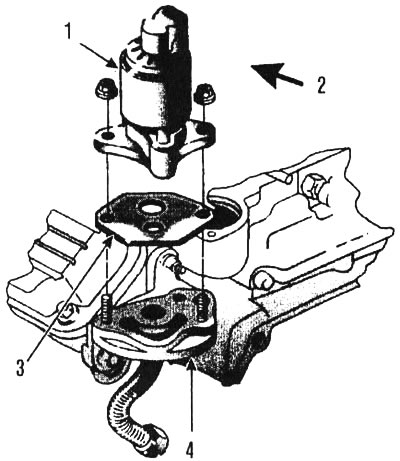
30. Having unscrewed two nuts, remove the EGR valve from the intake manifold (see illustration).

7.30. Details on the EGR valve installed on 3.8L engines since 1993: 1 - inline EGR valve, 2 - front, 3 - gasket, 4 - EGR valve adapter
31. Remove the gasket and clean the valve and adapter mounting surfaces. If necessary, remove traces of the old gasket material from them with a scraper.
32. With the new gasket and valve installed, tighten the nuts securely.
33. Connect the connector to the valve.
