Examination
1. Raise the front of the vehicle and secure it to the stands. Apply the parking brake and block the rear wheels to prevent the vehicle from rolling off the stands.
2. Perform a visual inspection of the rubber seals. Check for damage, traces of grease leakage. If damaged, the ball joint must be replaced.
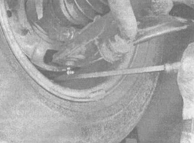
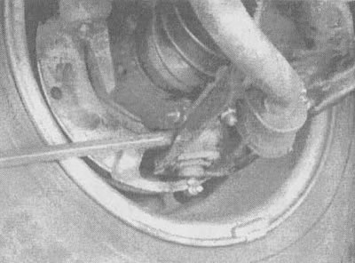
3. Insert a large pry bar under the ball joint and try to push the ball joint up. Next, position the pry bar between the steering knuckle and the suspension arm and press down (see illustrations). If any movement is felt during these checks, this indicates ball joint wear.

8.3a. Check if there is any mutual movement of the ball joint and the steering knuckle (indicated by an arrow) when trying to push them | 
8.3b. With the pry bar between the steering knuckle and the ball joint, press down and see if there is any play in the ball joint (if play is noticeable, replace the ball joint) |
4. Have your assistant rock the wheel vertically.
5. Separate the lower suspension arm from the knuckle (see section 5). fingers (do not use pliers here) try to tilt your finger in the socket. If the pin turns, replace the ball joint.
Replacement
6. Loosen the wheel nuts. Raise the front of the vehicle and secure it to stands. Apply the parking brake and block the rear wheels to prevent the vehicle from rolling off the stands. Remove the wheel.
7. Separate the suspension arm from the steering knuckle (see section 5). Temporarily insert the ball joint pin back into the knuckle (in a free state). This will make it easier to remove the ball joint after step 9, and will also hold the assembly while drilling out the rivets.
8. Using a 1/8" bit, drill a hole in the center of each rivet connecting the ball joint and suspension arm. Be careful not to damage the protective cover of the constant velocity joint during the drilling process.
9. Using a 1/2" drill bit, drill out the head of each rivet. Work slowly and carefully so as not to deform the holes in the suspension arm.
10. Loosen the nuts of the bushing clamps securing the anti-roll bar to the suspension arm (do not turn the nuts all the way). Pull the suspension arm and ball joint down to remove the ball joint pin from the steering knuckle, then slide the ball joint out of the suspension arm.
11. Place new ball joint on suspension arm and insert bolts (included with the new ball joint) at the top of the suspension arm. Tighten the bolts to the torque specified in the instructions for the new ball joint.
12. Insert the ball joint into the steering knuckle, fit the nut, tighten it to the torque specified in the specifications of this chapter, and insert a new cotter pin. It may be necessary to tighten the nut slightly to align the hole in the pin with the hole in the nut. Do not loosen the nut to allow the cotter pin to be inserted.
13. Tighten nuts of fastening of collars of plugs of the stabilizer of cross-section stability to the suspension arm the moment specified in specifications of this chapter.
14. Install the wheel, lower the vehicle and tighten the wheel nuts to the torque specified in the technical data chapter 1. After that, it is necessary to check and, if necessary, adjust the installation of the front wheels.
