Remove the signal switch, unscrew the steering wheel mounting nut and remove the steering wheel. Loosen the screws and remove the steering shaft covers.
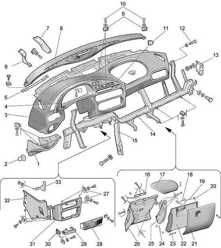
Remove the steering column switches. Loosen the four screws and remove the shield 4 (pic. 8-51) instrument panel assembly with switches by disconnecting the wiring harness pads from the switches.
Unscrew the two screws, disconnect the wiring harness pads and remove the instrument cluster.

Pic. 8-51. Removing the instrument panel:
1 - fuse block cover;
2 - buffer;
3 - instrument panel;
4 - instrument panel shield;
5 - shield mounting bracket;
6, 7 - left and right brackets for fastening the instrument cluster;
8 - insert of the instrument panel;
9 - spring nut;
10 - self-tapping screw;
11 - plug;
12 - bolt;
13 - bracket for the cross member of the instrument panel;
14 - cross member of the instrument panel;
15 - cross bar;
16 - lock latch;
17 - panel plug;
18 - glove box cover lock;
19 - axis of the castle;
20 - spring;
21 - glove box cover;
22 - inner panel of the glove box;
23 - axis of the glove box cover;
24 - lid opening limiter;
25 - lining of the glove box;
26 - glove box body;
27 - spring nuts;
28 - ashtray;
29 - service shelf;
30 - service shelf link;
31 - overlay of the instrument panel console;
32 - screen of the instrument panel console;
33 - console screen mounting bracket.
Remove upholstery of racks of a wind window.
Unscrew the two screws, remove the insert 8 of the instrument panel.
Loosen the four screws on the top of the instrument panel.
Remove the four screws and remove the instrument panel shelf.
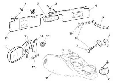
Unscrew five screws, remove facing 11 (pic. 8-52) floor tunnel assembly, remove the switches, disconnect the wiring harness pads.

Pic. 8-52. Removing rear-view mirrors and sun visors:
1 - self-tapping screw;
2 - internal rear-view mirror;
3 - long self-tapping screw;
4 - right sun visor;
5 - right handrail;
6 - right central handrail;
7 - middle ashtray;
8 - screw lining;
9 - screw;
10 - handrail plug;
11 - lining of the floor tunnel;
12 - motor reducer;
13 - facing of the handle of the external mirror;
14 - lining of the front door;
15 - gasket;
16 - left exterior mirror;
17 - left sun visor.
Loosen the four screws and remove the shield 32 (see fig. 8-51) instrument panel consoles. Unscrew the two screws and remove the overlay 31 of the instrument panel console.
Turn away two screws and remove a cover 21 of a ware box. Remove the glove box light, unscrew the two screws and remove the glove box body 26.
Unscrew the four screws securing the instrument panel cross member to the body bracket on the left and right and remove the instrument panel.
Install the instrument panel in reverse order.
