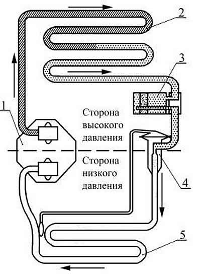
The operation of the air conditioner is possible only when the car engine is running. The principle of operation can be reduced to the following. Compressor 1, fig. 8-67, the refrigerant is constantly compressed and circulated. When compressed, the gaseous refrigerant turns into a liquid state, condensing in a heat exchanger-condenser with the release of heat. Further, during the reverse transition to the gaseous state (evaporation), heat is absorbed in the evaporator heat exchanger.

Pic. 8-67. The scheme of the air conditioner:
1 - compressor;
2 - capacitor;
3 - receiver;
4 - thermostatic valve (TRV);
5 - evaporator;
"stripes" - compressed gas with high pressure and temperature;
"points" - liquid phase of the refrigerant;
"white" - foggy phase and superheated steam.
The evaporator 5 located in the passenger compartment constantly reduces the air temperature. coolant transfer "hidden" heat into condenser 2, located outside the passenger compartment, and is released from it. This cycle is continuously repeated and, accordingly, heat is constantly removed from the passenger compartment to the atmosphere. The controls and actuators allow you to maintain the desired microclimate.
Attention: the air conditioning system of a CHEVROLET NIVA car uses R 134a refrigerant.
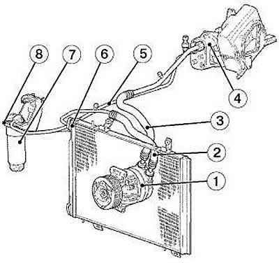
Compressor 1, fig. 8-68, is the main and most complex unit of the system. The compressor compresses a low temperature, low pressure refrigerant gas into a high temperature, high pressure gas. The compressor is mounted on the engine bracket on the right side.
The compressor is driven by a V-ribbed drive belt from the car engine through an electromagnetic clutch. When voltage is applied to its winding, the driven disk and pulley rotate synchronously, setting the compressor shaft in motion.
The compressor is lubricated with special compressor oil circulating throughout the system along with the refrigerant. AT41244 compressor oil is used in the air conditioning system (ISO 150).
- The volume of refrigerant, for refueling the air conditioning system - 0.65 kg.
- The volume of compressor oil is 0.22 l.

Pic. 8-68. Installation diagram of air conditioner units:
1 - compressor;
2 - injection pipeline;
3 - low pressure pipeline;
4 - evaporator;
5 - high pressure pipeline;
6 - capacitor;
7 - receiver-drier;
8 - condenser pipeline.
The condenser 6 of the air conditioner is aluminum. It condenses (transition to a liquid state) refrigerant pumped by the compressor with the release of heat into the atmosphere. For better airflow, the condenser is installed in front of the radiator of the cooling system.
Evaporator 4 is an aluminum heat exchanger. The transition of the refrigerant from liquid to gaseous state (evaporation) occurs in it with the absorption of heat. The evaporator is installed in the instrument panel in the path of the incoming air flow, which reduces its temperature.
Receiver-drier 7 is installed on the outlet pipeline of the condenser in front of the evaporator and serves as a reservoir for liquid refrigerant, cleans it from impurities and water. The receiver-drier can be equipped with a viewing window to control the amount of refrigerant.
The expansion valve is installed on the evaporator and controls the amount of refrigerant entering the evaporator. TRV is a device that provides a change in system performance depending on the conditions and mode of operation.
The pressure sensor sends a signal to the ECM to turn the A/C on/off based on the pressure in the high pressure line.
