Removing the battery (see Removing the battery).
We remove the starter (see Removing the starter).
Drain the oil from the gearbox (see Changing the oil in the gearbox).
Removing the front wheel drive (see Removing the front wheel drive).
Disconnect the wiring harness from the reverse light switch (see Removing the reverse light switch).
Before unscrewing the bolts securing the gearbox housing to the cylinder block, mark their position.
This will simplify the subsequent installation of the gearbox, since the lengths of the bolts and the hexagons of their heads are different.
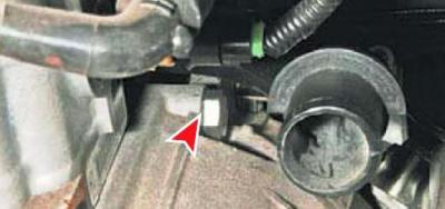
With the "19" head, we unscrew the bolt securing the gearbox housing to the engine block, located under the inlet pipe of the coolant pump (for clarity, the coolant hose is removed).
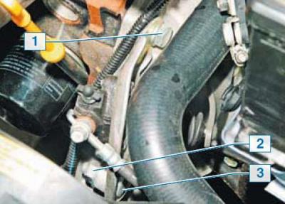
With the "19" head, we unscrew the bolt 1 and the nut 2 of the bolt 3 of the bracket for the clutch release cylinder, holding the bolt 3 with a wrench of the same size.
We remove the rod of the working cylinder from the hole of the lever of the clutch release shaft..
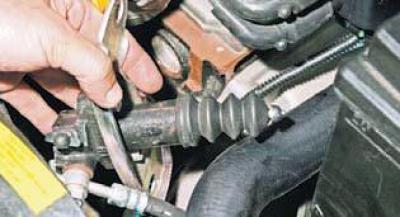
... and without disconnecting the hydraulic drive, we remove the bracket with the cylinder from the gearbox.
In order not to disturb the adjustment of the gearbox control drive, we mark with paint the axial and angular position of the tip of the gear change mechanism relative to the control rod.
We loosen the nut of the bolt of the terminal connection of the control rod with the tip (see Gearbox control drive adjustment).
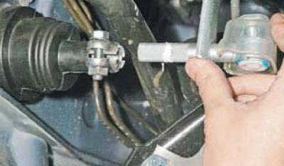
We remove the tip from the thrust hole.
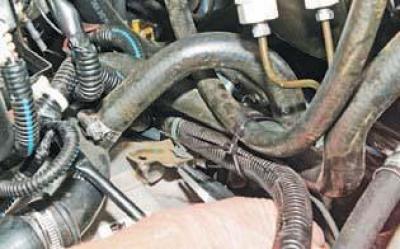
Using pliers, we compress the fastening clamp of the wiring harness clamp to the gearbox bracket and remove the wiring harness from the bracket.
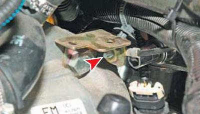
Using the "10" head, unscrew the bolt securing the "ground" wire tip.
We disconnect the block of wires of the engine management system from the vehicle speed sensor (see Removing the vehicle speed sensor).
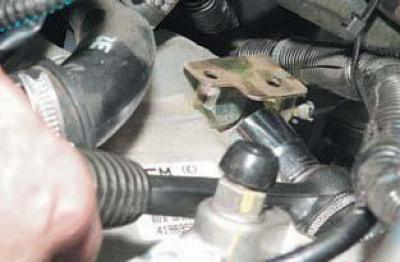
Using the "19" head, we unscrew the bolt securing the bracket and the gearbox housing to the engine block and remove the bracket with the bolt.
We take out the outlet hose of the heater radiator from the gearbox holder.
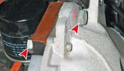
With the "19" head, we unscrew the two bolts of the front crankcase mounting.
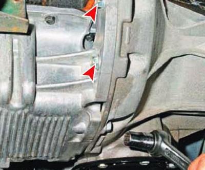
With the "14" head, we unscrew the two bolts of the front and the bolt of the lower fastening of the gearbox housing to the engine sump.
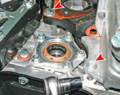
With the "14" head, we unscrew the bolt securing the gearbox housing to the engine sump and the "19" key - the bolt securing the crankcase to the cylinder block.
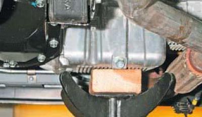
We install an adjustable stop under the engine sump by placing a wooden spacer and stop under the gearbox housing.
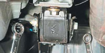
Using the "17" wrench, unscrew the nut of the bolt securing the gearbox bracket to the rear support of the power unit, holding the bolt with the "14" wrench.
We take out the bolt.
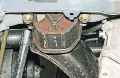
Using the "14" head, we unscrew the two bolts securing the left support of the power unit to the side member.
We lower the gearbox on an adjustable stop.
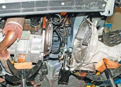
We take the gearbox away from the engine and remove it together with the left support.
Install the gearbox in reverse order.
Before installation, we apply a thin layer of SHRUS-4 grease on the splined part of the input shaft.
After installing the gearbox, fill it with oil.
If necessary, adjust the gearshift drive (see Gearbox control drive adjustment).
When removing or installing the gearbox, the gearbox input shaft must not be supported on the petals of the clutch housing pressure spring, so as not to damage them.
