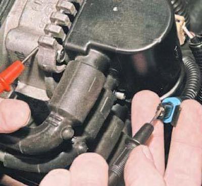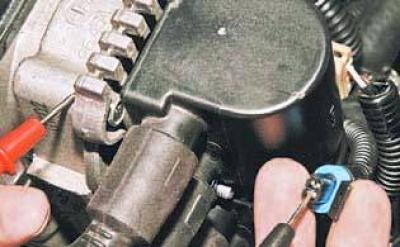
We connect the tester probes to the output "B" and the "mass" of the engine.
With the ignition on, we measure the voltage of the sensor input signal circuit.
The device should fix the voltage of 4.5-5.5 V.
If the voltage does not match, check the health of the circuit (open and short to ground) between terminal "B" of the wiring harness block and terminal "M28" of the computer harness block.

By connecting the tester probes to terminal "A" of the block and the "mass" of the engine, we measure the resistance of the "mass" circuit.
With a good sensor ground circuit, the device should detect a resistance of less than 1 ohm.
The reason for the increased resistance may be an unreliable connection in the pads connected to the sensor or to the computer.
If the sensor circuits are OK, the computer is faulty.
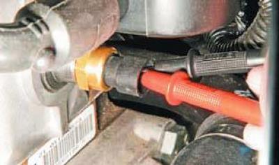
To test the coolant temperature sensor..

... we connect the tester probes to the sensor terminals.
We measure the resistance of the sensor for two values of the coolant temperature - an unheated and a warm engine.
We compare the obtained values with the control ones (see table).
For a more accurate check of the sensor, it must be removed (see Removing the coolant temperature sensor).
We lower the sensor into a vessel with water and heat the vessel.
We measure the resistance of the sensor at different temperatures.
The temperature is controlled by a thermometer.
We compare the obtained values with the control ones (see table).
Control values of resistance DTOZH at different temperatures of the coolant (tentatively)
| Coolant temperature,°С | Resistance, Ohm |
| 100 | 180 |
| 90 | 240 |
| 80 | 330 |
| 70 | 470 |
| 60 | 670 |
| 50 | 970 |
| 45 | 1 200 |
| 40 | 1 460 |
| 35 | 1 800 |
| 30 | 2 240 |
| 25 | 2 800 |
| 20 | 3 520 |
| 15 | 4 450 |
| 10 | 5 670 |
| 0 | 9 420 |
| -4 | 12 300 |
| -10 | 16 180 |
| -15 | 21 450 |
| -20 | 28 680 |
If the measured resistance values do not match the control values, the sensor must be replaced.
