With the ignition off, disconnect the block of the wiring harness of the engine control system from the phase sensor (see Removing the phase sensor).
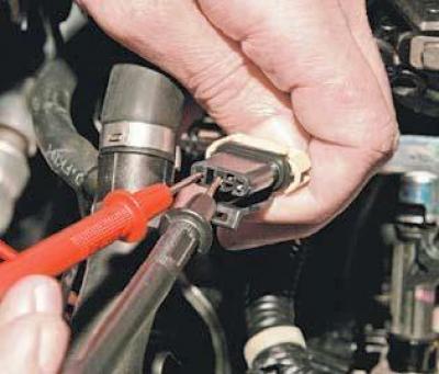
To check the power supply circuit of the sensor..

... we connect the tester probes to the terminals "B" and "C" of the wiring harness block.
With the ignition on, the voltage must be equal to the voltage of the on-board network.
Otherwise, check the integrity of fuse F14 (15A) mounting block located in the cabin, and the health of the circuit (open and short to ground) between terminal "C" of the wiring harness block and the mounting block.
We also check the health of the circuit between terminal "B" of the wiring harness block and "ground".
If the circuits are working and there is no voltage, the computer is faulty.

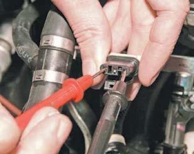
We connect the tester probes to the terminals "A" and "C" of the block of the wiring harness.
With the ignition on (and in the absence of a phase sensor signal) the tester should fix the voltage between terminals "A" and "C" about 6.5-7.0 V (when the voltage at the battery terminals is 12.0 V).
Otherwise, check the health of the circuit (open and short to ground) between terminal "M26" of the ECU harness block and terminal "A" of the wiring harness block.
If the circuits are working and there is no voltage, the computer is faulty.
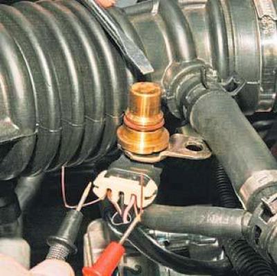
To check the phase sensor, dismantle it (see Removing the phase sensor) and connect the wiring harness to the sensor.
From the side of the input of the wires into the block, we insert two pieces of wire into its sockets corresponding to the terminals "A" and "C" so that there is contact between them and the terminals of the wires.
Set the tester to measure AC voltage (0-20 V).
We connect the tester probes to the wire segments.
Turning on the ignition..

... we pass several times in front of the sensor rod with a steel plate.
At the same time, at a serviceable sensor, the device should record abruptly changing voltage values.
Replace the defective sensor with a new one.
