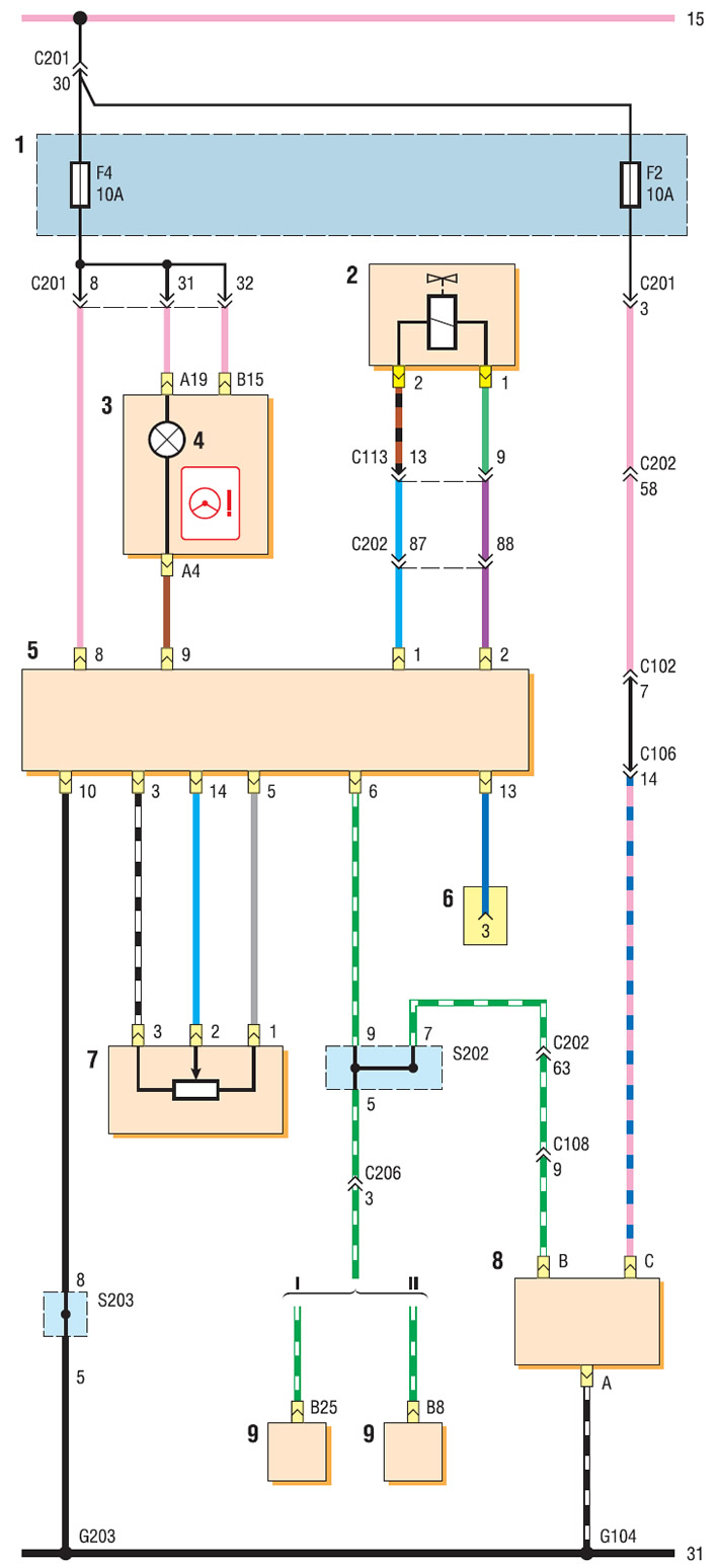
Connection diagram of the power steering control system: I - with Sirius D4 ECU; II - with ECU MR-140 or HV-240; 1 - mounting block fuses in the cabin; 2 - electromagnetic needle valve; 3 — a combination of devices; 4 - hydraulic booster malfunction indicator; 5 - hydraulic booster control unit; 6 - diagnostic connector; 7 - steering wheel sensor; 8 - vehicle speed sensor (manual gearbox); 9 - automatic transmission control unit
