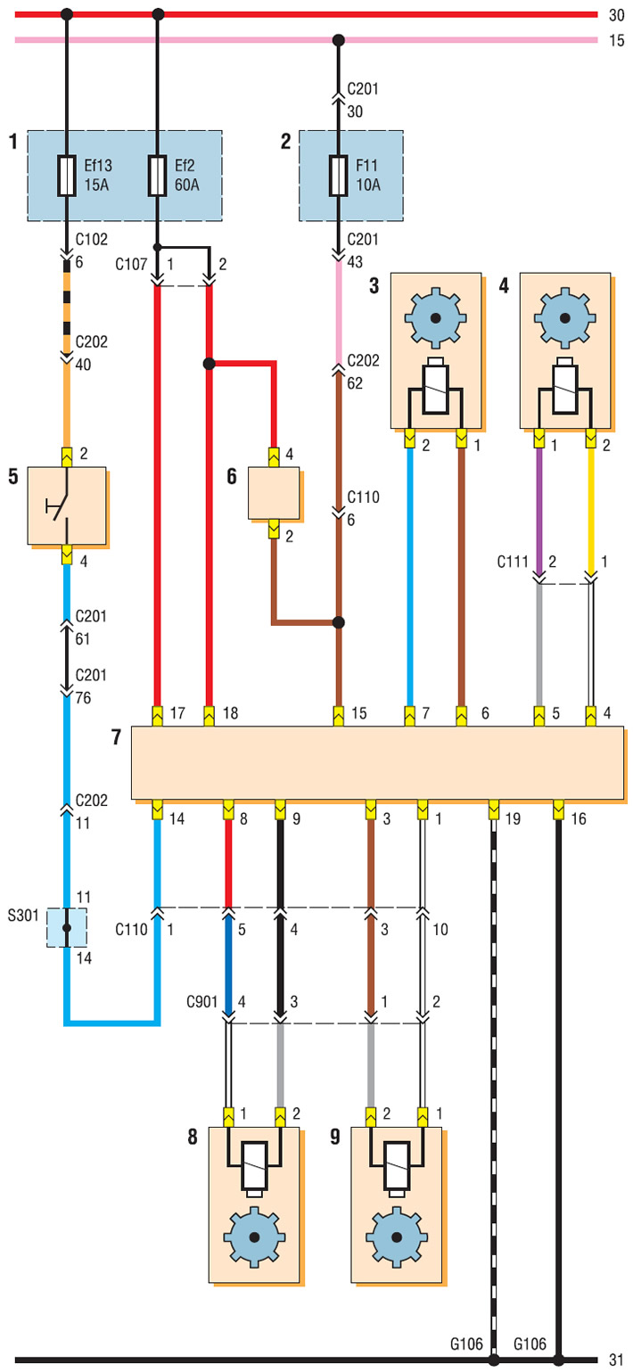
ABS control unit wiring diagram (Start): 1 - mounting block of relays and fuses in the engine compartment; 2 - mounting block fuses in the cabin; 3 - speed sensor of the left front wheel; 4 - speed sensor of the right front wheel; 5 — the switch of signals of braking; 6 - ABS diagnostic connector; 7 - ABS control unit; 8 - left rear wheel rotation sensor; 9 - right rear wheel rotation sensor

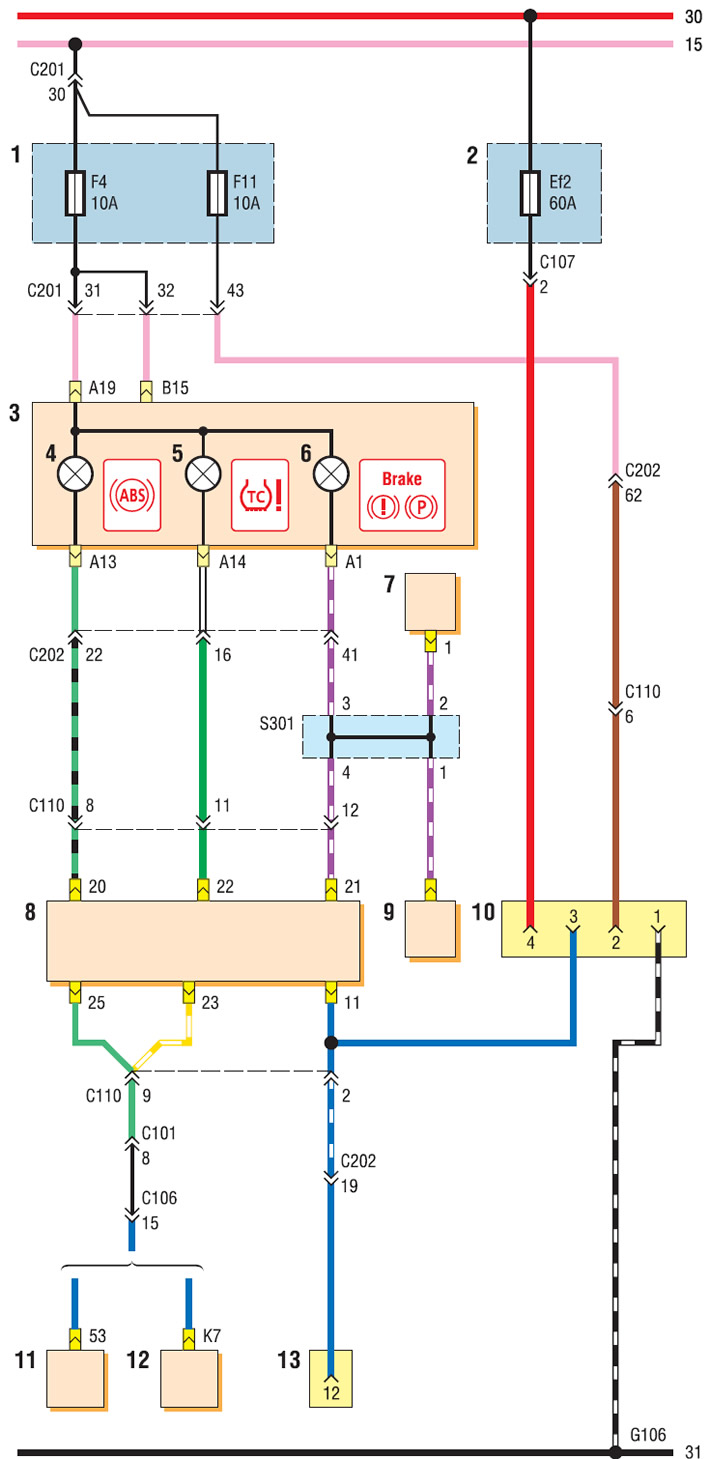
ABS control unit wiring diagram (ending): 1 - mounting block fuses in the cabin; 2 - mounting block of relays and fuses in the engine compartment; 3 — a combination of devices; 4 - ABS malfunction indicator; 5 - signaling device for malfunction of the anti-slip system; 6 - signaling device for turning on the parking brake and malfunctioning of the brake system; 7 - brake fluid level sensor; 8 - ABS control unit; 9 - parking brake indicator switch; 10 - ABS diagnostic connector; 11 - ECU Sirius D4; 12 - ECU MR-140; 13 - diagnostic connector
