The rim marking, for example, 16x6.5J 5x10⁵ DIA 56.6 ET39, is deciphered as follows:
- 16 - rim diameter in inches;
- x - deep rim;
- 6.5 - rim profile width in inches;
- J - rim flange shape (J-shaped);
- 5x10⁵ - number and diameter of mounting holes, mm;
- DIA 56.6 - hub hole diameter, mm;
- ET39 - disc overhang 39 mm.
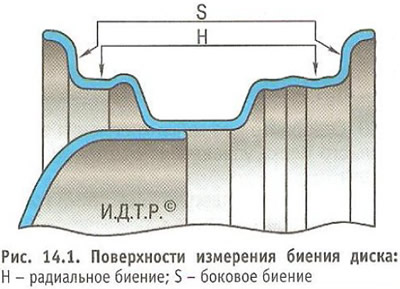
Attach the disc without tire to the axle of the balancing device. Install the measuring tip of the dial indicator first on the radial, and then on the lateral inner surface of the disk, on which the tire bead rests (pic. 14.1).

Note: The maximum runout of the steel disk: I = 1.015 mm; S = 1.143 mm. The maximum runout of an alloy wheel: H = S = 0.762 mm.
Slowly rotate the balancer disc with your hands while reading the indicator. At the same time, do not take into account the deviation of the indicator arrow from local protrusions or recesses on the disk.
If the maximum runout is greater than the specified values, replace the disc.
