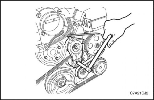
Removal procedure
1. Remove the decorative engine cover. See «Decorative engine cover» in this section.
2. Remove upper intake manifold. See «Upper intake manifold» in this section.
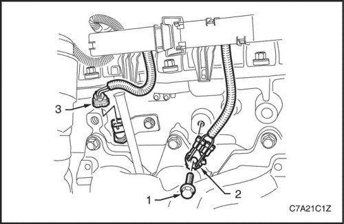
3. Remove bolt (1) connections on "mass" (2) to the cylinder head (row 1: 2 places; row 2: 1st place).
4. Bank 2: Disconnect wiring harness connector (3) engine coolant temperature sensor.
5. Disconnect the engine wiring harness retaining tabs on the sides of the cylinder head covers.
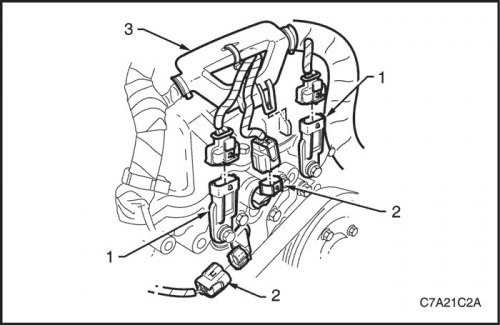
6. Disconnect connectors (1) camshaft position sensor (SMR).
7. Disconnect connectors (2) camshaft control valve.
8. Detach the fastener (3) engine wiring harness located on the front cylinder head cover.
9. Remove the ignition coil assembly. See Part 1F3, Engine Controls - HFV6 3.2L.
10. Remove the engine wiring harness from the cylinder head covers.
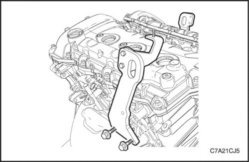
11. Remove the engine lift bracket bolts from the cylinder head.
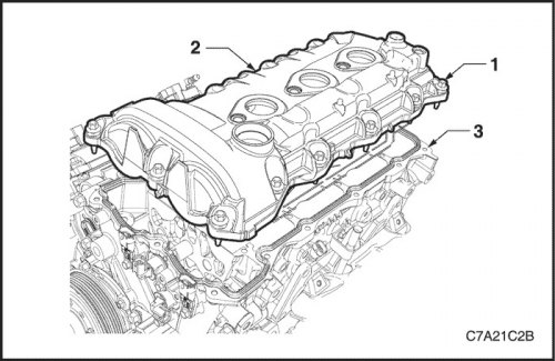
12. Remove bolt (1) mounts (13 places) cylinder head covers (2) from cylinder head (3).
13. Remove the cover and discard the seal.
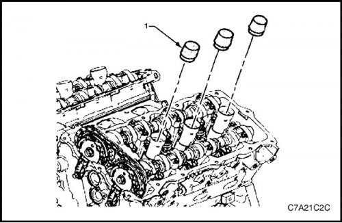
14. Install the EN-46101 tool on the spark plug tubes (1), to prevent dirt from entering the combustion chambers.
Cleaning and inspection
1. Clean the cylinder head cover with a suitable cleaning solvent and blow dry with compressed air.
2. Inspect the cover for cracks or deformation.
3. Check for damaged spark plug tube seals.
4. If the cylinder head cover is damaged in such a way as to affect its sealing and dirt protection, the cover must be replaced.
Installation procedure
1. Installation is carried out in the reverse order to the removal of parts.
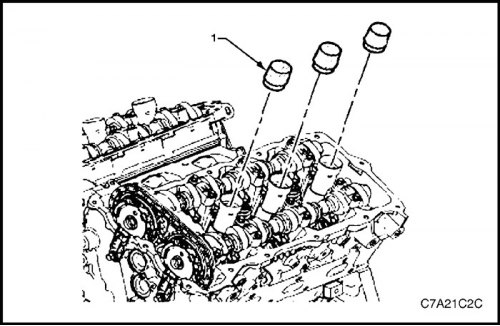
2. Install fixtures EN-46101 (1) on the spark plug tubes, if not already done.
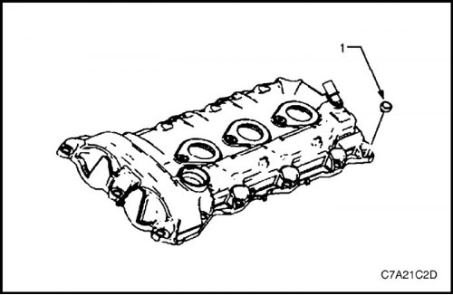
3. Make sure the bushing (1) (13 places) correctly positioned in the hole provided for it.
4. Wipe with a clean, lint- and thread-free cloth the sealing surface of the cylinder head and cover.
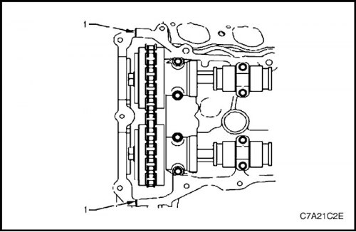
5. Ensure that the new seal is correctly positioned on the cylinder head cover. Apply sealant (RTV) on the line of the junction of the front cover of the engine (1).
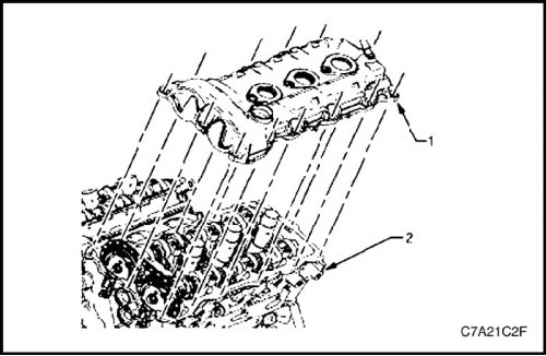
6. Install cover (1) cylinder heads to their intended location on the head (2).
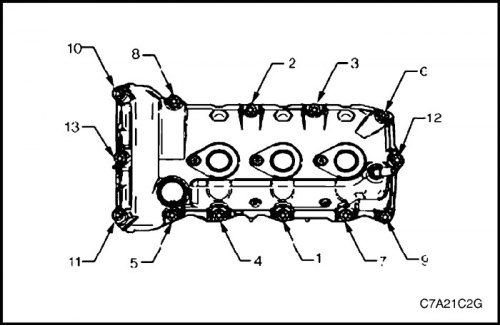
7. Install cover bolts (1) cylinder heads in the sequence shown.
Tighten
Tighten the cylinder head cover fixing bolts to 10 Nm (89 lb-in.).
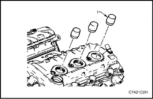
8. Remove tool EN-46101 (1).
9. Tighten the remaining fasteners.
Tighten
Tighten the connection bolt to "mass" engine torque 10 Nm (89 lb-in.).
Tighten the engine lift bracket bolts to 50 Nm (37 lb-ft).
10. Connect all remaining connectors.
