Attention! Do not smoke or use open flames in areas where work is being done on the fuel system. When working on the fuel system, disconnect the negative battery cable, except for tests that require battery voltage.
Removal procedure
1. Remove the common fuel rail assembly. See «Common rail» in this section.
2. Clean rail pressure sensor interface with suitable degreasers and dry with compressed air.
Note: Cleaning agents must not get into the electrical connector.
3. Remove the rail pressure sensor along with the gasket, if equipped.
Attention! Immediately after removing the fuel lines, put a cap on the common rail pressure sensor to prevent dust contamination. Even small amounts of dust can clog nozzles.

Installation procedure
Attention! Do not blow air from the spray gun inside the injector sleeves, the common fuel rail and the injection pump. In case of contamination, wipe the dusty area with oiled paper.
Attention! Do not wipe with wipes inside the injector sleeves, the common fuel rail and the injection pump. In case of contamination, wipe the dusty area with oiled paper.
1. Inspect and clean the threads and sealing surface of the rail.
2. Inspect and clean the threads and sealing surface of the rail pressure sensor.
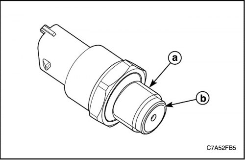
3. Apply to thread (a) and cutting edge (b) rail pressure sensor grease Ft1v27 (only a thin film of lubricant).

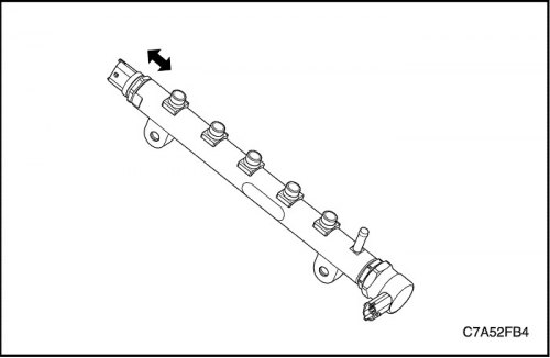
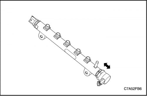
4. Install the rail pressure sensor to the common rail.
Tighten
Tighten rail pressure sensor to 70 Nm (51.6 lb-ft).
5. Perform fuel bleeding. See «Fuel pumping» in this section.
6. Reset EEPROM values for ZFC when replacing (Zero fuel trim), using a diagnostic tool.

