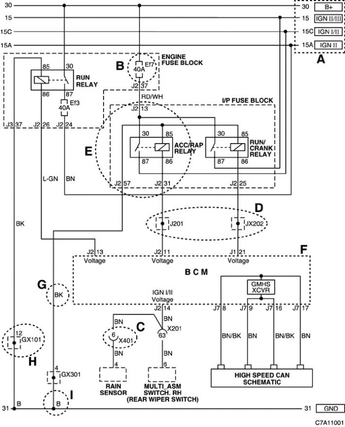
1) Contents of the electrical diagram (chain)
|
POSITION
|
EXPLANATION
|
|
A
|
- Upper horizontal lines: power supply, power supply Power lines: 30, 15, 15A, 15C |
|
IN
|
- EF7 or AF3 or F2
|
|
C
|
- Connector (X101~X902)
|
|
D
|
- Wiring harness connection
|
|
E
|
Component internal circuit (relay) (component name, pin number) |
|
F
|
- Internal component circuit (controller) (component name, pin number and wiring diagram) |
|
G
|
Wire harness color |
|
H
|
- Ground harness block
|
|
I
|
- Bottom horizontal line: Ground line
|
2. Chain symbols
|
CONDITIONAL
SYMBOL
|
MEANING
|
|
X
|
connector
|
|
E
|
Fuse in the fuse box in the engine compartment,
|
|
A
|
Fuse in the fuse box in the engine compartment, add.
|
|
F
|
Fuse in the fuse box on the dashboard
|
|
G
|
Weight
|
|
J
|
contact block
|
3. Purpose of power lines (number)
|
Power supply number
|
Power Supply Status
|
|
15
|
Battery powered (B+) when ignited in position "ON" And "ST" (IGN II/III)
|
|
15A
|
Battery powered (B+) when ignited in position "ON" (IGN II)
|
|
30
|
Battery powered (B+) directly, regardless of ignition position
|
|
31
|
Ground connected to battery (-)
|
4. Color coding of wire harnesses
|
Reduction
|
Color
|
Reduction
|
Color
|
|
BN
|
Brown
|
L-BU
|
light blue
|
|
GN
|
Green
|
RD
|
Red
|
|
VT
|
Violet
|
BU
|
Blue
|
|
PK
|
Pink
|
YE
|
Yellow
|
|
WH
|
White
|
GY
|
Grey
|
|
Or
|
Orange
|
BK
|
Black
|
|
L-GN
|
light green
|
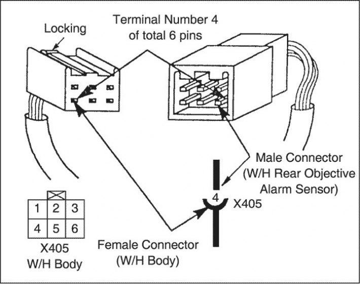
5. How to check the connector pin number
The pin number is indicated according to the connector number. Example: pin number 4 of connector X405

