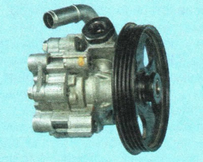
The steering of the car consists of a steering wheel, a steering column, a steering gear, a working fluid pump, two steering rods and two of their tips connected by ball joints to the steering knuckles of the front suspension.

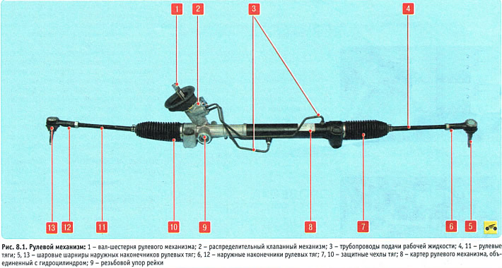
The pressure of the working fluid in the hydraulic booster is created by a vane-type pump, which is mounted on the engine bracket and is driven by a V-ribbed belt from the water pump pulley, which in turn is also driven by the V-ribbed belt from the crankshaft pulley. From the tank, the high-pressure working fluid is pumped to the distribution valve mechanism 2 (pic. 8.1), mounted on the steering gear housing and connected to the steering column. When the steering wheel is turned, the valve mechanism connects one of the cavities of the hydraulic cylinder, made in the crankcase 8 of the steering mechanism, with the high pressure line, and the second with the fluid drain pipe into the tank. The toothed rack connected to the piston of the hydraulic cylinder moves in the steering gear housing under the influence of the gear and the pressure difference in the hydraulic cylinder. Moving, the rack through the steering rods transfers the force to the steering knuckles, which leads to the rotation of the front wheels of the car. If the amplifier fails, the ability to drive the car remains, but the force on the steering wheel increases.

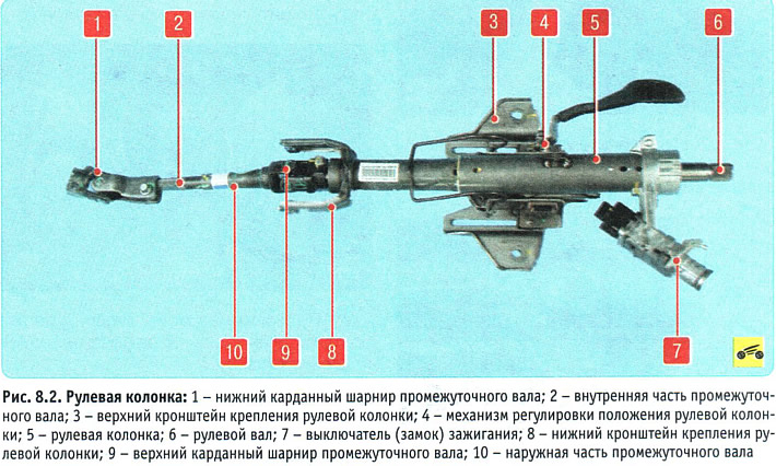
A safety steering column is installed on the car (pic. 8.2) with a mechanism 4 for adjusting its position along the reach and angle of inclination. The intermediate shaft consists of two parts 2 and 10 with a spline connection. When the body is deformed during a frontal collision, the parts of the shaft telescopically slide into each other, reducing the possibility of injury to the driver from hitting the steering wheel. The intermediate shaft is connected to the steering shaft and the gear shaft of the steering mechanism by cardan joints 9 and 1, respectively. On the steering column there is an ignition switch 7 with an anti-theft device that blocks the steering wheel shaft from turning, as well as controls for headlights, direction indicators, horn, washer and cleaner for the windshield and tailgate glass, combined into a block of steering column switches.

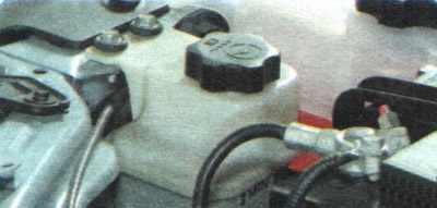
The power steering reservoir is installed in the front of the engine compartment on the upper cross member of the radiator frame and is connected by hoses to the power steering pump and to the working fluid return line. To control the liquid level, level marks are applied to the translucent wall of the tank.

Tie rods are attached to the steering rack and to the steering knuckles of the front suspension with ball joints 5 and 13 (see fig. 8.1). Tie rods are secured against turning in the ends with locknuts. By rotating the steering rod in the ball joint relative to the tip, the toe-in of the steered wheels is adjusted.
