Disassembly
1. Remove the output shaft bearing using a universal puller.
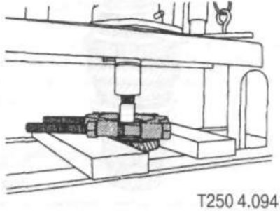
2. Remove retaining ring (35), thrust disc (34), needle thrust bearing (33) (see fig. T250 4.092).
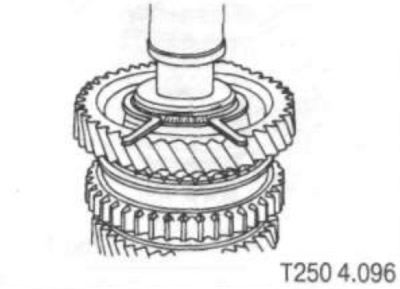
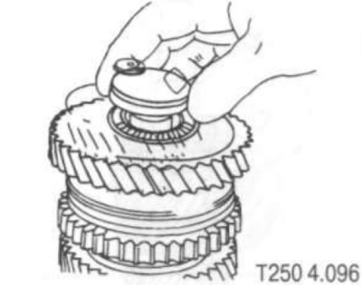
3. Remove the first driven gear (32), first gear needle bearing (31) (see fig. T250 4.092).
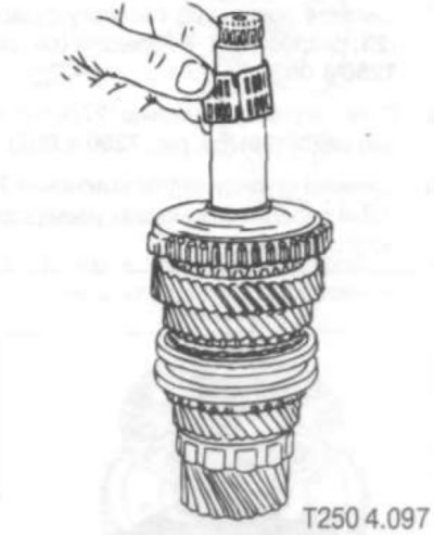
4. Remove the three synchronizer rings (28). (29) And (30) 1st gear (see fig. T250 4.092).
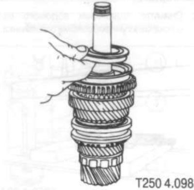
5. Remove the 1st and 2nd gear clutch.
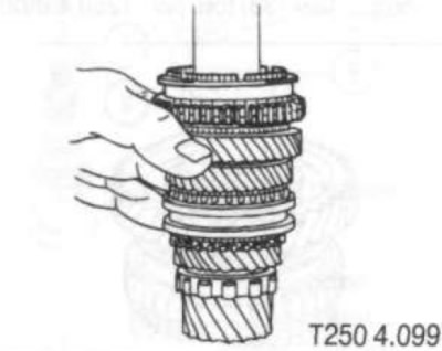
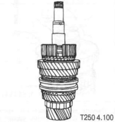
6. Remove the retaining lugs from the 1st and 2nd gear clutch hub.
7. Remove the spring spacer crackers (23) from 1st gear (see fig. T250 4.092).
8. Remove retaining ring (27) and composite puck (26) (see fig. T250 4.092).
9. Remove the 1st and 2nd gear clutch hub using a universal puller.
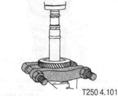
10. Remove the three synchronizer rings (22), (21) And (20) 2nd gear (see fig. T250 4.092).
11. Remove 2nd driven gear (19) (see fig. T250 4.092).
12. Remove the 2nd gear needle bearing (18) (see fig. T250 4.092).
13. Remove retaining ring (17) and compound washer (16) (see fig. T250 4.092).
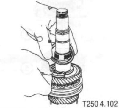
14 Remove the 3rd gear (13) and synchronizer ring (13) 3rd gear (see fig. T250 4.092).
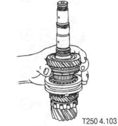
15. Remove the needle bearing (15) driven gear 3rd gear (see fig. T250 4.092).
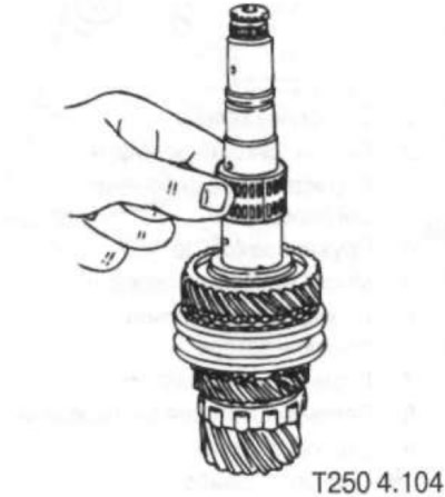
16. Remove the clutch (8) inclusion of 3rd and 4th gears (see fig. T250 4.092).
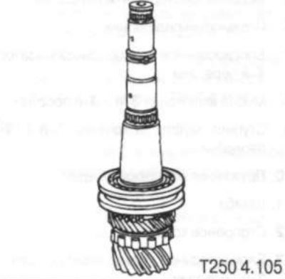
17. Remove the spring spacer (10) crackers-clamps from the 3rd gear.
18. Remove the clamps (9) clutches for 3rd and 4th gears.
19. Remove retaining ring (12) and compound washer (11).
20. Remove the hub of the 3rd and 4th gear clutch using a puller and remove the spring spacer of crackers from the hub (10) (see fig. T250 4.092)
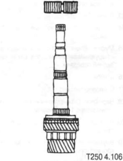
21. Remove the 4th driven gear (5) (see fig. T250 4.092).
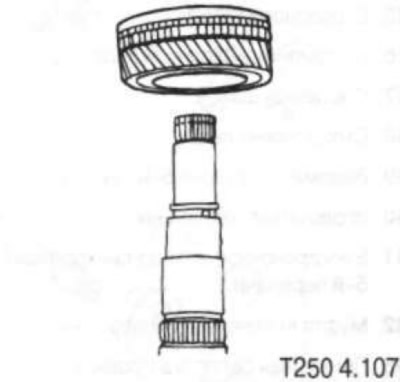
22. Remove 4th gear needle bearing, circlip (4) and thrust washer (3) (see fig. T250 4.092)
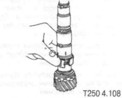
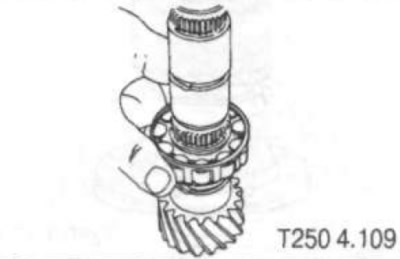
23. Remove the bearing (2) output shaft (see fig. T250 4.092).
Assembly
Reassemble in the reverse order of disassembly.
Note: When installing gear shift clutches, pay attention to the position of the clutch. This applies in particular to the 1st and 2nd gear clutch, since this clutch is also the driven gear for the reverse gear.
