Disassembly
1. Remove the cylinder head along with the intake and exhaust manifolds.
2. Remove the coolant temperature sensor.
3. Remove the exhaust manifold heat shield.
4. Remove the exhaust manifold.
5. Remove the exhaust manifold gasket.
6. Remove the exhaust manifold studs.
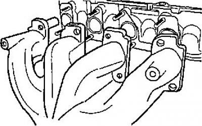
7. Remove the spark plugs.
8. Remove the intake manifold.
9. Remove the intake manifold gasket.
10. Remove the intake manifold studs.
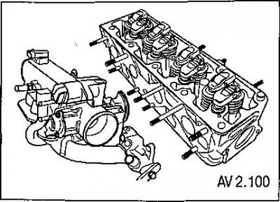
11. Remove the thermostat housing screws.
12. Remove the thermostat housing.
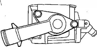
13. Remove the thermostat gasket and thermostat.
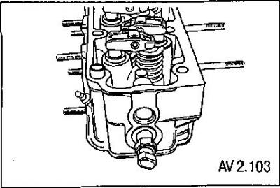
14. Using a valve spring compressor, compress the valve springs.
15. Remove the crackers and remove the upper plates of the valve springs.
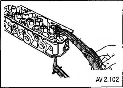
16. Remove valve springs.
17. Remove valve stem seals.
18. Remove valves.
20. Remove the centering sleeves of the camshaft housing.
Parts repair
For the described engines, the manufacturer provides for steam recovery «guide sleeve - valve stem» using valves with oversized stems. In this case, the worn bushing is restored by the deployment method to repair dimensions. Work of this complexity should only be entrusted to a qualified mechanic.
|
Camshaft |
||
|
Inlet cam lift |
6.12 mm |
|
|
Exhaust lobe lift |
6.12mm |
|
|
End runout |
0.09-0.21mm |
|
|
Camshaft journal outer diameter |
№1 |
39.445 mm |
|
№2 |
39.700 mm |
|
|
№3 |
39.945 mm |
|
|
№4 |
40.200 mm |
|
|
№5 |
40.445 mm |
|
|
Bearing outside diameter |
№1 |
39.500 mm |
|
№2 |
39.750 mm |
|
|
№3 |
40,000 mm |
|
|
№4 |
40.250 mm |
|
|
№5 |
40.500 mm |
|
Cylinder head inspection
1. Clean the plane mating with the head gasket.
2. Check the cylinder head gasket and the mating surfaces of the cylinder head and block for pits, leaks, corrosion, and gas blow-by into the cooling jacket.
3. Check the cylinder head for cracks.
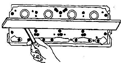
5. Determine, using a set of probes and a straight edge, the deviation from the flatness of the head plane mating with the gasket, which should not exceed 0.025 mm.
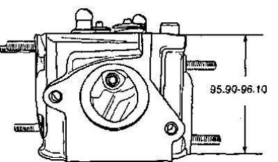
6. Measure the block head height. The cylinder head height should be between 94.70-95.65 mm. If the cylinder head height is less than 94.7 mm, it should be replaced.
7. Check all threaded holes for damage or contamination.
8. Inspect valve seats for excessive wear and burnout.
|
valve mechanism |
||
|
Valve drive control method |
Hydraulic valve clearance compensator |
|
|
Valve face taper angle (between the generatrix and head plane) |
45" |
|
|
Valve seat taper angle |
45' |
|
|
Reference beat (max, all) |
0.03mm |
|
|
End runout (max, all) |
0.03mm |
|
|
Seat face width |
Inlet |
1.3-1.5mm |
|
Outlet |
1.6-1.8mm |
|
|
Valve guide inner diameter |
7.030-7.050 mm |
|
|
Valve stem diameter |
7 mm |
|
|
Valve disc diameter |
Inlet |
38.0 mm |
|
High school graduation |
31.0 mm |
|
|
Valve spring length under load |
Open valve 625 +25 N |
21.5mm |
|
Closed valve 275 + 15N |
31.5mm |
|
Valve guide reconditioning
1. Determine the actual wear in a pair «sleeve - valve stem». With a gap exceeding 0.1 mm, this friction pair needs to be replaced. This diagnostic operation should only be carried out by a qualified mechanic.
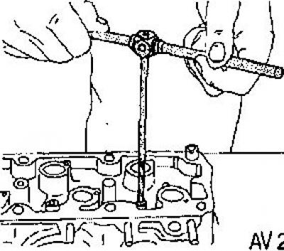
2. Oversize code is stamped on the valve guide and valve stem end. The table shows the standard and repair dimensions, the designation of the reamer used by authorized service stations, and the content of the codes applied to the bushings and valves. There are two types of codes: the code applied when assembling a new engine, and the code applied to the bushing during repair.
|
Size |
Scan |
Code applied to new engine parts |
Code applied to engine parts during repair |
|
Standard |
- |
- |
TO |
|
0,075 |
KM-253 |
1 |
K1 |
|
0,150 |
Km-254 |
2 |
K2 |
|
0,250 |
KM-255 |
- |
A |
Ream the guide bush hole. The direction of deployment is from the top side of the cylinder head. Once deployed, cross out the code printed on the sleeve and apply a new code.
Valve seat reconditioning
1. Finish the working surface of the valve seats.
The closing surface of the valve seats is restored using three conical cutters:
- cutter for processing the working surface of the saddle: 45°;
- cutter for processing the upper correction angle: 30°;
- cutter for processing the lower correction angle: 60°;
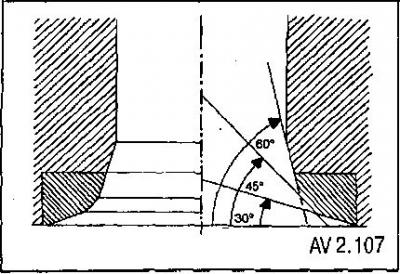
Valve seat width:
- intake: 1.3-1.5 mm;
- outlet: 1.6-1.8 mm.
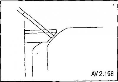
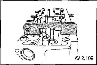
2. Check the position of the valve stem end after installing the valve (without special gauges, this work must be done by a qualified mechanic).
3. If the stem end is higher (closer to the camshaft axis), replace the valves with new ones and then check the stem end position again.
4. If the valve stem end is still higher despite changing the valves, replace the cylinder head.
Valve Inspection
1. Inspect the valve for wear, crushing of the upper end of the stem.
2. Inspect the valve cotter grooves and oil seal for wear.
3. Inspect the valve heads for burnouts and cracks.
4. Inspect valve stems for wear, nicks, and scratches.
5. Inspect the valve stem - it is not long. wives to have curvature.
6. Inspect the valve closing cone. If the wear of the contact cone is so great that the resurfacing produces a sharp edge at the junction of the conical and flat surfaces of the valve head, the valve should be replaced.

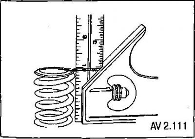
7. Inspect the valve spring. If the ends of the valve spring are not parallel, replace the valve spring.
8. Measure the height of the valve spring. If the valve spring height is not within specifications, replace the valve spring.
9. Inspect the valve spring seating surfaces for wear or grooves. Replace if necessary.
Valve grinding
1. Check that the valve head cone is free of burnouts.
2. The valve can only be reground twice. Do not grind the end of the valve stem.
3. The angle between the generatrix of the valve cone and the plane of the head is 46".
Lapping of valves
If the wear of the closing cone of the valve is not too great, the valve should be lapped against the restored closing cone of the valve seat (as a rule, during valve operation, the closing surface of the connecting rod bearings becomes wider: up to 4-5 mm). If at the same time there is no deep groove on the cone, then it is possible to grind the valve to the restored seat without grinding the cone.
The valve is lapped using special lapping pastes based on corundum.
In this case, the valve, installed in the guide sleeve, performs reciprocating movements with simultaneous rotation to the right and left, alternately. Such movements are necessary for the formation of oblique lapping lines, located crosswise. During the lapping process, periodically turn the valve in the seat to ensure uniform lapping. Lapping can be considered complete when a uniform matte gray annular contact strip is formed on the closing surface of the valve, equal in width to the closing surface of the seat.
Assembly
1. Install the camshaft housing dowels.
2. Lubricate the valve stems with engine oil.
3. Install valves.
4. Install valve stem seals.
5. Install the valve springs.
6. Compress the valve springs and install the cotters.
7. Install the valve cover.
8. Install thermostat.
9. Install the thermostat housing
10. Install the thermostat housing screws and tighten them to 20 Nm.
11. Install the intake manifold studs.
12. Install the intake manifold gasket.
13. Install the intake manifold and tighten the nuts to 25 Nm.
14. Install the spark plugs and tighten to 40 Nm.
15. Install the exhaust manifold studs.
16. Install the exhaust manifold gasket.
17. Install the exhaust manifold and tighten the nuts to 25 Nm.
18. Install the exhaust manifold heat shield and tighten the screws to 15Nm.
19. Install the coolant temperature sensor and tighten to 20 Nm.
20. Install the cylinder head along with the intake manifold and exhaust manifold.
